TRCI-02 / TRANSMISSION + REFLECTION

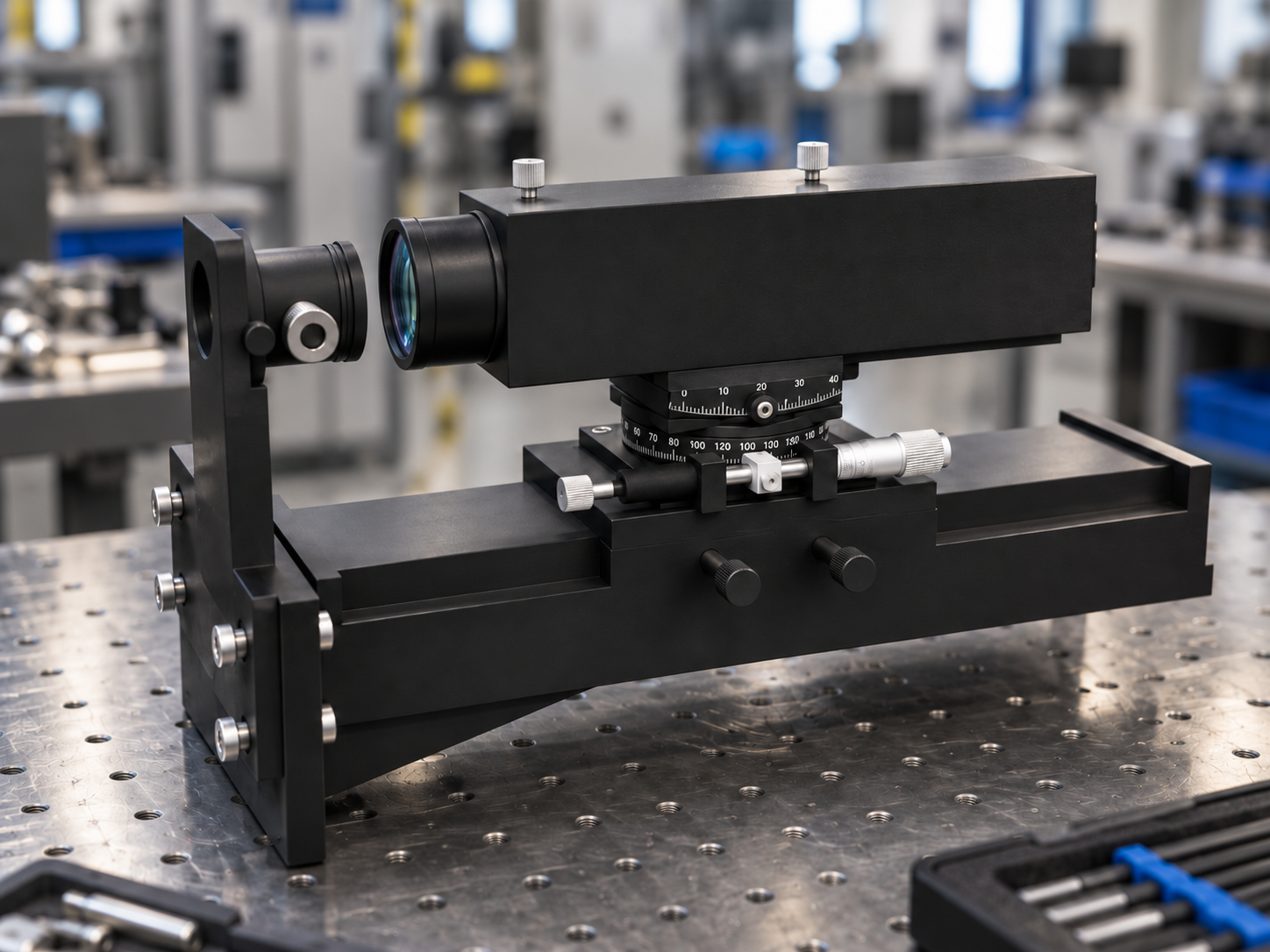
Integrated transmission and reflection centering instrument

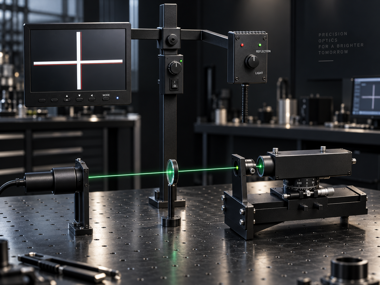
Switch between transmitted and reflected measurements to suit different lens edging processes.

Integrated transmission and reflection centering instrument
01Transmission mode
02Reflection mode

Product introduction

Two measurement methods in one instrument.

Integrated transmission and reflection centering instrument

This instrument adds reflection measurement to transmission inspection, integrating both methods in one device. Operators can switch modes according to lens structure and process requirements.

Transmission mode observes the image formed by light passing through a lens to evaluate its overall transmitted centering error. Reflection mode observes the reflected crosshair from a target spherical surface to assess how far its center of curvature is from the rotation reference axis. The methods provide complementary references for edging and optical centering.

Operators can use transmission when the process calls for a transmitted reference, switch to reflection to inspect a selected surface, then switch back. This reduces equipment changes and preparation between inspection tasks.

Operating guide

Using reflection measurement

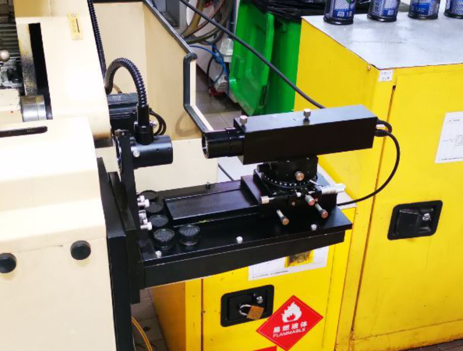
Centering instrument installed on a lens edging machine
01

Prepare the measurement

Clean the lens, fixture and measuring optics. Check the spindle and centering mechanism, and leave a safe distance between the measuring head and workpiece. Select the appropriate optical configuration for the lens and keep the zoom setting unchanged during measurement.

02

Mount the part and find the image

Secure the lens or mounted assembly in the fixture. Roughly center it, then adjust the measuring head and focus until the target surface’s reflected crosshair is clear in the field of view. Reflection centering requires focus at that surface’s center of curvature.

03

Set the image and capture the trace

Adjust illumination so the crosshair edges are sharp without saturation. Set a measurement area that contains the image throughout a full rotation. Capture at least one revolution at the specified spindle speed, then check that the trace is continuous and crosshair detection is stable.

04

Adjust manually and remeasure

Stop the spindle after each measurement and make a small adjustment according to the fixture procedure. Rotate and measure again to compare the trace.

05

Secure and confirm

Once the result meets the process requirement, lock the adjustment mechanism and check that locking has not caused a noticeable shift.

Working principle

Two modes observe two different optical references.

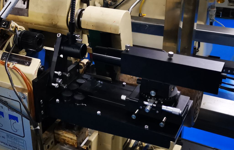
Centering instrument installed on a lens edging machine
01

Transmission: evaluate the transmitted focus

A collimated beam passes through the test lens and forms a crosshair image at its focal plane. The measuring optics send the image to the CCD. As the lens rotates around the reference axis, software analyses the crosshair position and path to evaluate the transmitted focus relative to that axis.

02

Reflection: measure a selected spherical surface

In reflection mode, the measuring optics focus at the target surface’s center of curvature. The CCD captures its reflected crosshair. If that center is offset from the rotation reference axis, the rotating lens produces a periodic image trace. Its size helps the operator adjust the surface center.

03

Mode switching: match the process

The two modes observe the transmitted focus and spherical center of curvature respectively. After switching, adjust the observation focus and measurement settings to match the current task.

Reflection mode

How the reflected image forms a trace

Reflection measurement establishes an optical reference for precise centering during lens processing and mount adjustment.

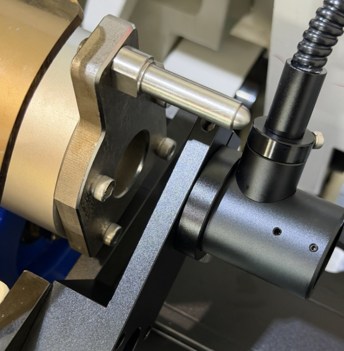
Reflection light source mounted on the machine
Reflection light source
01

Imaging: observe the center of curvature

A light source illuminates the crosshair reticle. Light passes through the objective and focusing optics toward the test surface. Adjust the head or focusing mechanism to match the measuring focus to the spherical surface’s center of curvature.

Surface normals pass through the center of curvature. Under suitable conditions, reflected light returns along the measuring path and forms a clear crosshair image on the CCD, allowing its position to be read.

02

Rotation: turn centering error into an image trace

When the surface center of curvature lies on the spindle axis, the reflected crosshair stays nearly stationary as the lens rotates. If it is offset, the image follows a periodic path. Under ideal conditions the path is circular, with radius proportional to the distance from the reference axis.

A smaller trace indicates that the surface center is closer to the rotation reference axis. The change in position during rotation is the key observation; the screen center itself only has measurement meaning after reference calibration.